Torque Converter Testing Challenges
In the development of a torque converter, there are several engineering parameters on each of the internal components that must be understood: temperatures, fluid pressures, strains, and potential cavitation.
In torque converters, the stator, turbine, and clutch are rotating inside of the pump and cover, which is also rotating inside the transmission housing. This presents a big challenge to get data off each component using an inductively powered, wireless telemetry system. IR Telemetrics has developed a unique measurement system which overcomes all of these challenges and allows engineers to get the desired data from these internal components.
Two Stage Inductive Power and Microwave Telemetry Transmission System
IRT’s inductively powered microwave telemetry system uses two stage inductive powering. Starting from a stationary main exciter coil, which is coupled to the pickup coils mounted on the rotating cover, one of these coils supplies power to the cover mounted transmitter. The other two pickup coils mounted on the impeller then become exciter coils coupled to pickup coils mounted to the turbine and stator rotating inside the cover. These internal pick-up coils then supply power to the microwave transmitters mounted on the turbine and stator, which then transmit the RF signal through intermediate absorbing and re-radiating antennas in the pump and cover to get the signal to stationary receiving antennas located in the transmission bell housing.
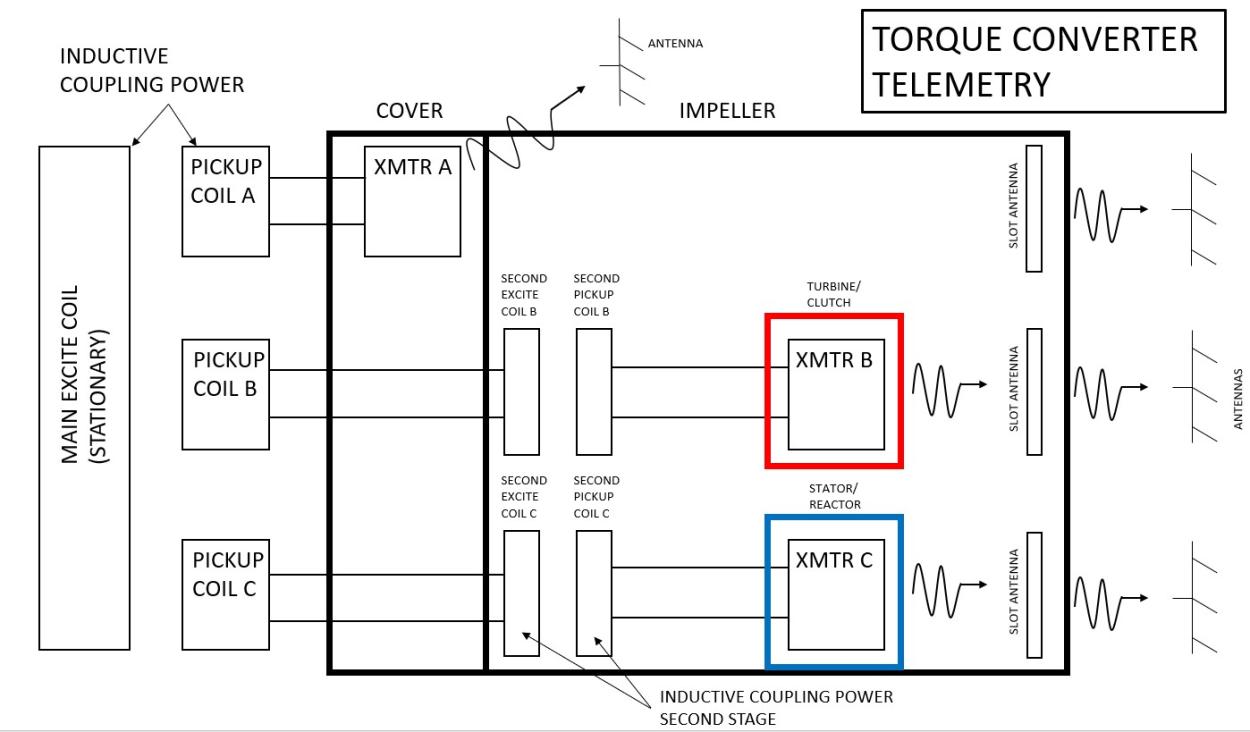
In this example, torque converter pressure, stator pressure, and turbine pressure were measured simultaneously with three transmitters (29 channels total). IRT’s microwave transmitter and inductive power converter electronics are well suited for this application as they can withstand high temperatures, up to 185 deg C. They can also be submersed in the transmission fluid and withstand the rotational inertial loading and fluid pressure encountered in an application like this.
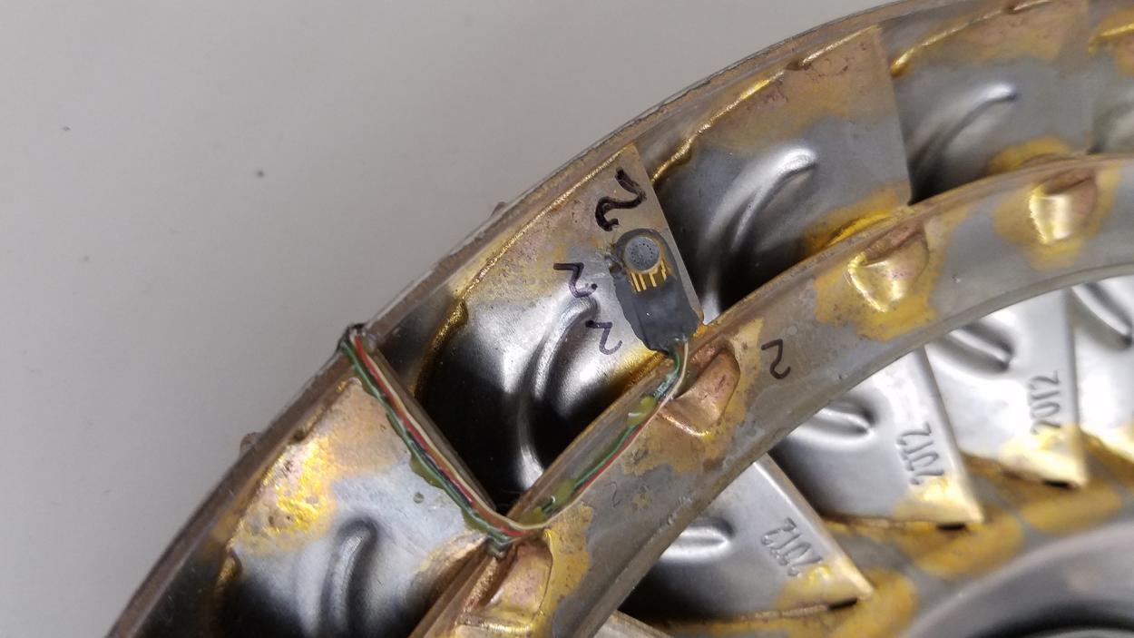
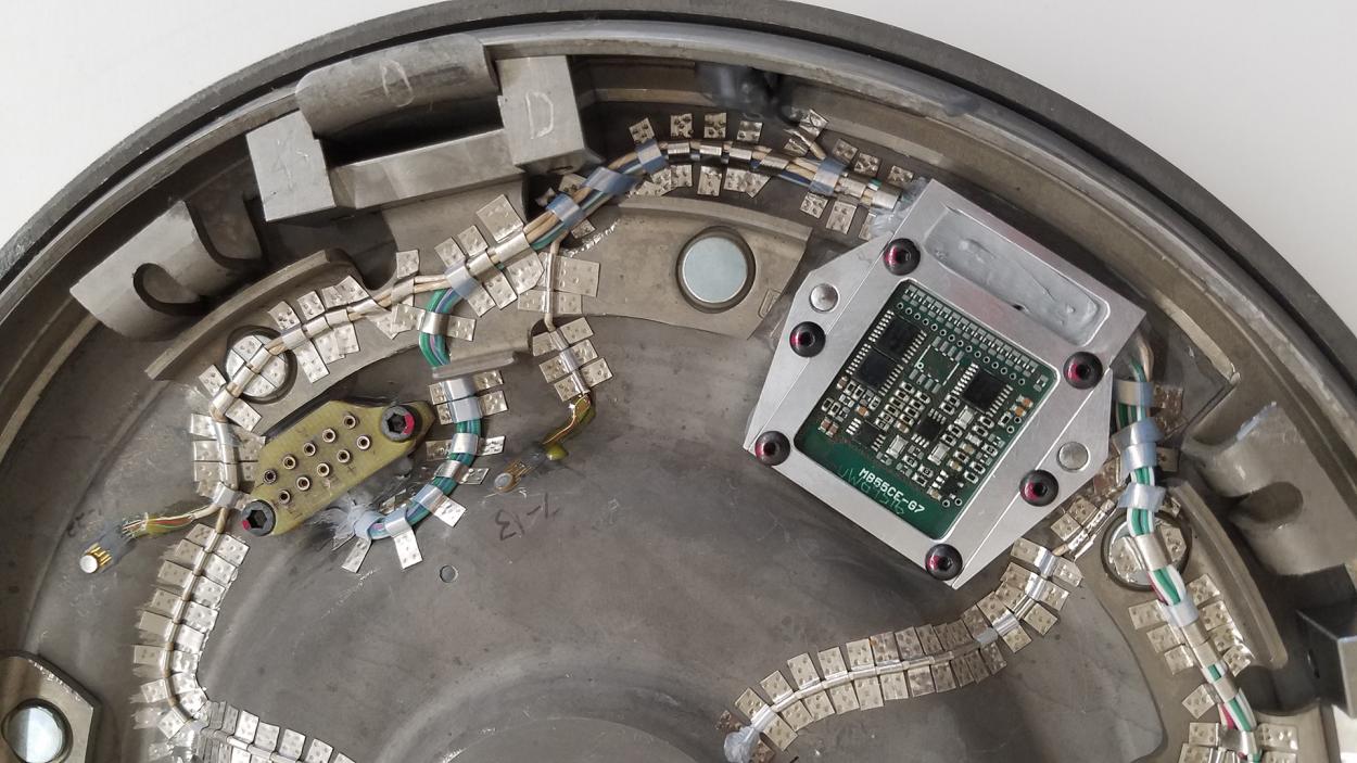
Miniature piezo resistive pressure transducers were installed at the desired locations on each component to measure pressure. These transducers have also been successfully used by IRT to detect the onset of cavitation occurring inside the torque converter.
Special alloy straps were spot welded to secure all transducer wires and power leads. Custom built pin connecters were designed by IRT to facilitate the assembly of the components.
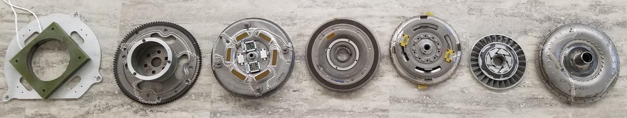
The illustration above shows the details of the instrumentation.
From left to right:
- Bracket Mounted Stationary Inductive Exciter
- Inductive Pick Up Coils(3 coils, 1 powering cover mounted transmitter and 2 powering two stage inductive power coils which power turbine and stator mounted transmitters)
- Torque Converter Cover(with absorbing / reradiating antenna slots)
- Lock Up Clutch
- Turbine (pressure measurement – 1 transmitter / 15 transducer locations)
- Stator(pressure measurement – 1 transmitter / 7 transducer locations)
- Impeller(pressure measurement – 1 transmitter / 7 transducer locations)
Although each torque converter has similar components, they can vary vastly in their internal design. IR Telemetrics, Inc. is the world’s leader in custom built telemetry systems for applications requiring unique approaches to the installation of wireless measurement systems. Contact us and we can develop and install a measurement system for your unique application and design, and provide you with the real-time measurements you require.